GEN II PRIUS - COMBINATION METER REMOVAL


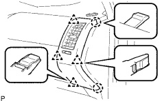
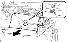
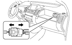
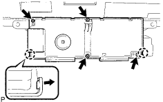
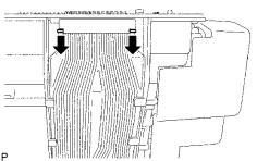
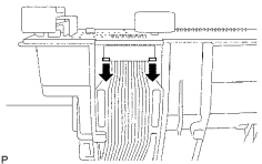
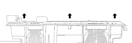
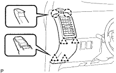
1. REMOVE NO. 1 INSTRUMENT PANEL REGISTER ASSEMBLY

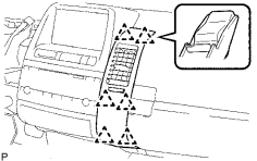
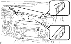
(a) Detach the 2 claws and 4 clips holding register assembly in by pulling straight out.
(NOTE: The easiest wayto do this is to wrap a butter knife in electrical tape so it will not scratch any plastic, and work it into the gap near the bottom, then use it as a lever to help unsnap it.)


2. REMOVE LOWER INSTRUMENT PANEL FINISH PANEL SUB-ASSEMBLY

(a) Remove the 2 screws.

(b) Disconnect the hood lock control cable. (NOTE: Much easier to just leave lower panel hanging by the hood release cable if possible!)

(c) Detach the 4 claws and 5 clips.

(d) Disconnect all connectors and remove the instrument panel finish panel.


3. REMOVE UPPER INSTRUMENT PANEL FINISH PANEL SUB-ASSEMBLY

(a) Detach the 3 claws and 4 clips.

(b) Disconnect the connector and remove the instrument panel finish panel.


4. REMOVE NO. 3 INSTRUMENT PANEL REGISTER ASSEMBLY

(a) Detach the claw and 5 clips.

(b) Disconnect the connector and remove the instrument panel register.


5. REMOVE NO. 4 INSTRUMENT PANEL REGISTER ASSEMBLY

(a) Detach the 6 clips and remove the instrument panel register.


6. REMOVE NO. 2 INSTRUMENT PANEL REGISTER ASSEMBLY

(a) Detach the 2 claws and 4 clips, and remove the instrument panel register.


7. REMOVE MULTI-DISPLAY ASSEMBLY

(a) Remove the 2 bolts.

(b) Pull display unit straight out.

(c) Disconnect the connectors behind display unit.


8. DISENGAGE LOWER GLOVE COMPARTMENT DOOR DASHPOT SUB-ASSEMBLY

(a) unsnap the dashpot arm from the lower glove compartment door by pulling to the right.


9. REMOVE GLOVE COMPARTMENT DOOR ASSEMBLY

(a) While pushing in the sides of the lower glove compartment door as indicated by the arrows in the illustration, open the door to release it from the 2 stoppers.

(b) Open the door until it is horizontal.


(c) Pull the lower glove compartment door toward the rear of the vehicle to detach the 2 hinges and remove the door.


10. REMOVE UPPER GLOVE COMPARTMENT DOOR

(a) Using a sharp pry tool, remove the 2 hole covers in the rear wall of the upper glove compartment.

(b) Remove the 2 screws.

(c) Detach the claw and 2 clips, and remove the glove compartment door.

11. DISCONNECT CENTER INSTRUMENT PANEL SPEAKER (only w/ JBL Sound System)


12. REMOVE FRONT PILLAR GARNISH CORNER PIECES

(a) Put protective tape as shown in the illustration.

Standard measurement:

Area

Specified Condition

A

2.0 mm (0.079 in.)

B

10.0 mm (0.394 in.)

C

50.0 mm (1.969 in.)

(b) Disengage the 5 claws to remove the corner piece.

(c) Repeat procedure for opposite side.


13. REMOVE FRONT PILLAR GARNISH COVERS

(a) w/o Curtain Shield Airbag:

(1) Remove the 2 clips to remove the pillar garnish cover.

(2) Repeat procedure for opposite side.


(a) w/ Curtain Shield Airbag:

(1) Gently pull out on the pillar garnish cover to disengage clip B and C.  NOTE: Clip A will not disengage!

(2) Using needle-nose pliers, rotate the tip of clip A 90 degrees, Then pull the pillar garnish cover away.

(3) Repeat procedure for opposite side.


14. DISCONNECT PASSENGER AIRBAG WIRING HARNESS CONNECTOR

(a) Slide white locking tab while gently pulling the yellow connector halves apart.

NOTICE:

When handling the connector, take care not to damage the airbag wire harness.


15. REMOVE INSTRUMENT PANEL TOP PAD

(a) Remove the 2 bolts from passenger airbag module. (under glovebox area)

(b) Disconnect left side wiring harness connectors.

(c) Free passenger airbag module wiring harness.

(d) Remove the 3 screws .

(e) Pull up the instrument panel to detach the 6 claws and 3 clips.

(f) Remove the instrument panel.

(g) Carefully place upside down on a soft blanket.

NOTICE:

When disassembling the combination meter assembly, eliminate static electricity by touching the vehicle body to prevent the components from being damaged.


16. REMOVE COMBINATION METER ASSEMBLY

(a) Remove the 5 screws and combination meter. You may have to also remove part or all of the adjacent bezel to clear the posts.


17. REMOVE COMBINATION METER CIRCUIT BOARD COVER

NOTICE:

When disassembling the combination meter assembly, eliminate static electricity by touching the vehicle body to prevent the components from being damaged.

(a) Remove the 4 screws.

(b) Release the 2 white claws of the cover, as shown in the illustration.

(c) Tilt the white plastic cover from the bottom up and out and remove it.


18. DISCONNECT NO. 1 FLEXIBLE CIRCUIT CONNECTION

(a) Using fingernails or a small tool, Slide both connector locks ~2mm in the direction indicated by the arrows in the illustration.


19. DISCONNECT NO. 2 FLEXIBLE CIRCUIT CONNECTION

(a) Using fingernails, Slide the connector locks in the direction indicated by the arrow in the illustration.


20. REMOVE COMBINATION METER CIRCUIT BOARD

NOTICE:

When disassembling the combination meter assembly, eliminate static electricity by touching the vehicle body to prevent the components from being damaged.

(a) Carefully remove main circuit board from housing by lifting it up. (NOTE: 3 silver screws stay in place!)

(b) Disconnect small connector on side by gently pulling it away in the direction of it's wiring.